Furnace temperature
The furnace temperature depends on the required charge temperature. The element temperature will exceed the furnace temperature by an amount determined by the element design.
Furnace power
Furnace power is calculated by determining the amount of power needed to heat the charge to a predetermined temperature within a specific time, including furnace losses and a safety margin.
Mode of operation
For continuously operating furnaces, it is generally sufficient to calculate the power required for the actual charge, considering the normal efficiency for that type of furnace. Assuming an efficiency of 70-80% to cover losses from an electric furnace, and adding a safety margin, an adequate input value may be obtained. For batch furnaces, required heat-up times and the heating capacity of the furnace must be considered when determining input power requirements. However, input power itself has minimal effect on energy consumption and efficiency. The decisive factor is heat losses, determined by the effectiveness of the insulation. A given mass requires the same amount of energy regardless of the total power.
The aim in selecting input power values is to provide sufficient power without being excessively high in relation to furnace size, as this would lead to unnecessarily high element temperatures, adversely affecting service life. LTM (low thermal mass) batch furnaces may require approximately 25% less input power.
Furnace voltage
Apart from small high-temperature furnaces, which usually operate on lower voltages via a transformer, most furnaces can be designed to operate at standard line voltage. The element thickness or cross-section also influences circuit design. For large cross-sections, furnace power should not be divided among too many parallel circuits. With three-phase AC power, a star (Y) configuration generally allows for larger cross-sections, while a delta (Δ) configuration requires smaller cross-sections. Therefore, elements in small furnaces should preferably be connected to a single-phase power source in series or through a low-voltage transformer.
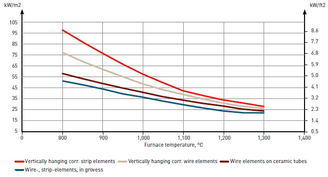
Furnace wall loading
In designing resistance elements, element temperature and material cross-section are crucial, as they significantly affect service life. The goal is typically to achieve maximum element life. Important factors include power concentration on the furnace wall, specific surface load of the resistance material, and heat transfer conditions. The wall area is usually calculated as the length multiplied by the height or width of the element-carrying wall, roof, or bottom.
Max recommended wall loading versus furnace temperature and different element configurations
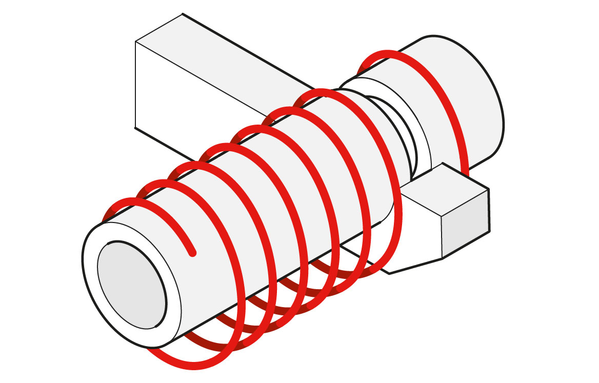
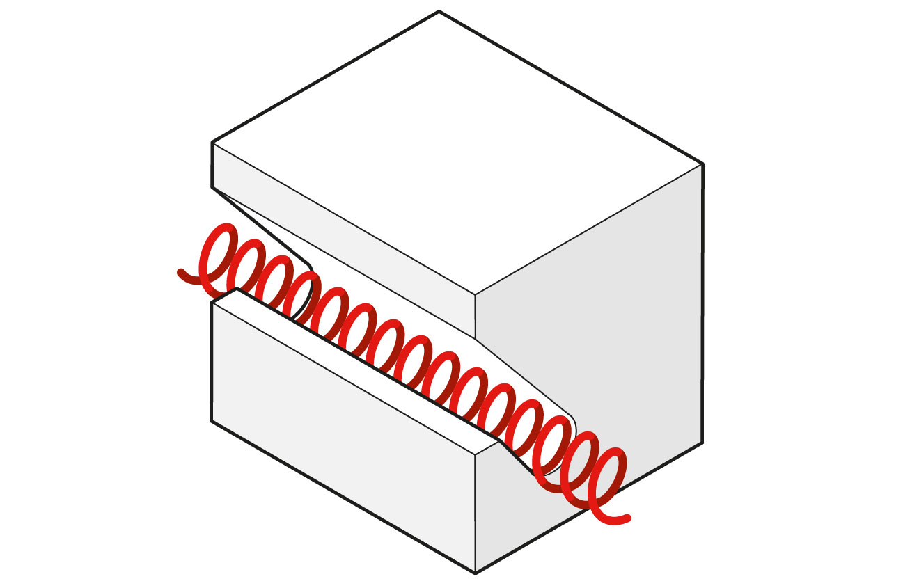
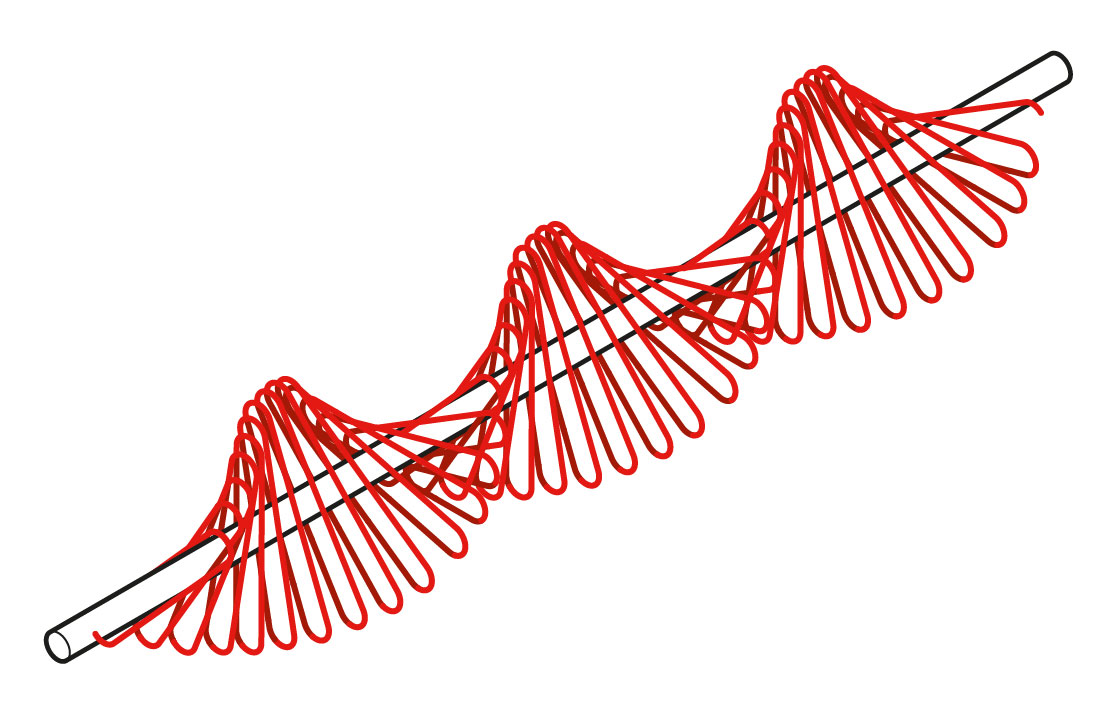
Overview: Furnace element types
Furnace heating element systems include wire and strip configurations. Designed for temperatures up to 1,300°C (2,370°F), they optimize performance through precise surface load and wall loading parameters.
| Wire elements | Strip element | |||||||||
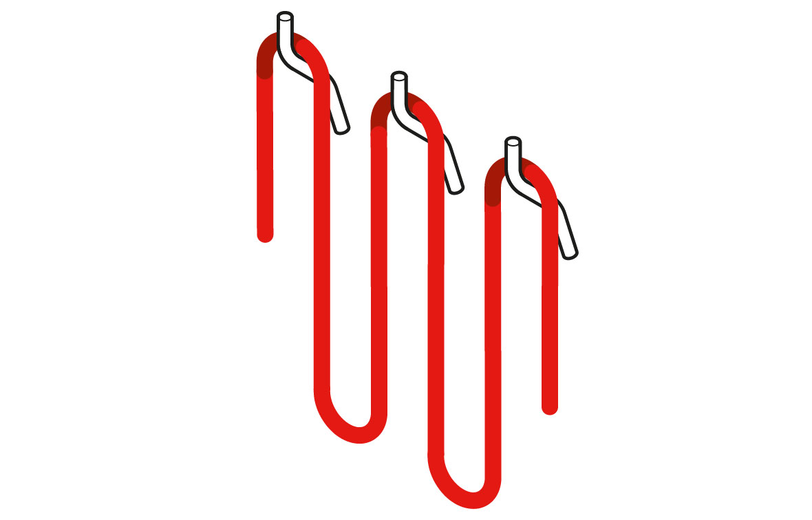
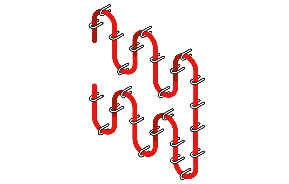
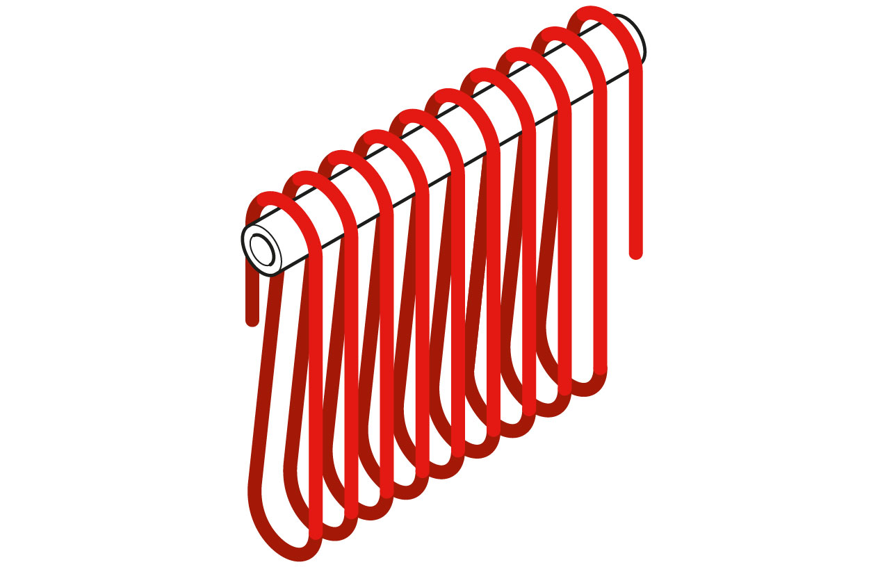
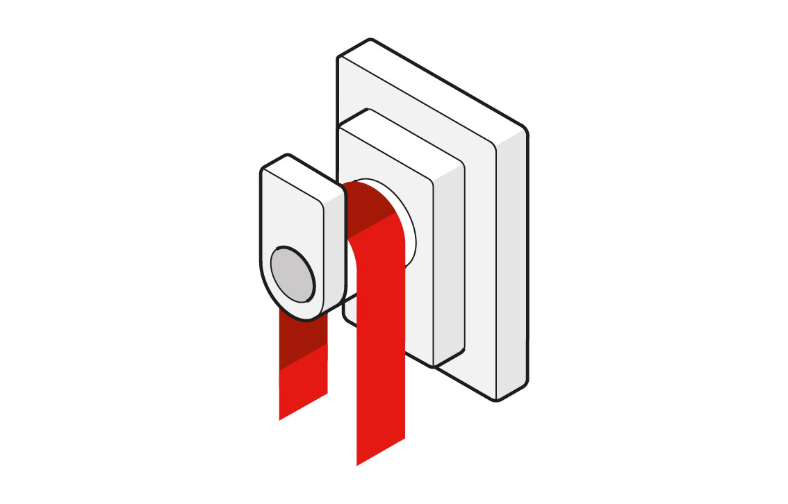
| Element types | Spiral | Spiral | Porcupine | Rod Over Bend | Corrugated | Looped | Deep-corrugated | Deep-corrugated | Deep-corrugated | Corrugated |
| Supports | Ceramic tubes | Grooves | Ceramic tubes | Metallic rods | Metallic staples | Ceramic tubes | Ceramic cup locks | Ceramic bushes | Ceramic tubes | Grooves |
 |
 |
 |
 |
 |
 |
 |
 |
|||
| Material | Silimanite | Chamotte grade 28 | Silimanite | Kanthal® APM | U-shaped Kanthal® nails |
Silimanite | Cordierite or mullite | Cordierite or mullite | Sillimanite | Chamotte grade 28 |
| Max. furnace temperature, °C | 1,300 | 1,250 | 800 | 1,300 | 1,300 | 1,300 | 1,300 | 1,300 | 1,300 | 1,300 |
| Max. wall loading at 1,000°C furnace temperature, kW/m2 |
40 | 35 | – | 50 | 50 | 60 | 60 | 60 | 60 | 20 - 40 |
| Max. surface load at 1,000°C furnace temperature, W/cm2 |
3 - 4 | 3 - 4 | – | 5 - 6 | 3 - 6 | 5 - 6 | 5–6 | 5–6 | 5–6 | 3 - 4 |
| Wire diameter, d, mm | 2.0 - 6.5 | 2.0 - 5.0 | 1.0 - 6.5 | >5.0 | 2.0 - 5.0 | >5.0 | – | – | – | – |
| Strip thickness, t, mm | – | – | – | – | – | – | 2.0–3.0 | 2.0–3.0 | 2.0–3.0 | 1.5–3.0 |
| Strip width, w, mm | – | – | – | – | – | – | 8–12 t | 8–12 t | 8–12 t | 8–12 t |
| Outer coil diameter, D, mm | 12 - 14 d | 5 - 6 d | – | – | – | – | – | – | – | – |
| Max. loop length at 1,000°C furnace temperature, mm |
– | – | – | 250 | 100 | 250 | 250 | 250 | 250 | 2 - 3 w |
| Min. pitch at max. loop length, mm | 3d | 2d | 3d | 40 | 40 | 40 | 50 | 50 | 50 | 1.5w |