By balancing these variables with material properties, designers can ensure optimal efficiency, reliability, and cost-effectiveness. Additionally, the chapter includes detailed guidelines for designing wire coil elements and outlines standard tolerances for wire dimensions and electrical resistance to ensure precision and consistency in manufacturing.
Content:
Appliance calculations
Furnace calculations
Design of wire elements
Appliance calculations
SUPPORTED WIRE
The typically used wire surface load, and in many cases, the element surface load is listed in the Appliance element types table. The element surface load is defined as the rating divided by the part of the element surface that is close to the energized wire and therefore has an elevated temperature.
Usually, a range of surface loads rather than a single figure is provided in these tables. The choice within this range depends on the requirements for the element, as well as on the voltage, rating, and dimensions available. A high voltage and a low rating will result in a thin wire, which, at the same temperature, has a shorter life than a thick wire, and therefore will require a lower wire surface load.
WIRE TEMPERATURE
For embedded and supported element types, the wire temperature depends on both the wire and the ele- ment surface load. For suspended element types, the element surface load, in most cases, cannot be defined. In addition to the surface load, factors such as ambient temperature, heat dissipation conditions, and the presence and location of other elements will influence the wire temperature, which in turn affects the choice of wire and element surface loads.
SURFACE LOAD
When calculating an element, voltage, and rating are typically known. The wire surface load is then chosen per the figures listed in the table. The wire surface is found as the ratio between the rating and the wire surface load.
SURFACE AND RESISTANCE
After calculating the resistance in the cold state, the ratio between the surface and the resistance is determined. This ratio is listed for all wire types and dimensions in this handbook, enabling easy identification of the correct wire size from the tables.
COIL AND WIRE DIAMETER
The ratio between the coil and wire diameter (O/d) must be calculated to ensure that the coil can be easily manufactured. Ideally, this ratio should be within the range of 5 to 12. For supported elements, this ratio must be compared with the deformation curve in the graph. When the coil length and diameter are known, the coil pitch can be estimated using Formula (10) in the Appendix. It is normally 2 to 4 times the wire diameter. For quartz tube heaters, a smaller pitch is typically used. Preoxidized coils made from Kanthal® FeCrAl in such elements can be used with a slight coil.
For a straight wire on a threaded firebar and many suspended-type elements, the wire length is fixed. The resistance per meter can be calculated, and the wire size determined from the tables in this handbook. If this results in a high surface load with ribbon, a wider and thinner ribbon of the same cross-section can be chosen.
METAL SHEATHED TUBULAR ELEMENT
The calculation of a metal-sheathed tubular element is more complex because the resistance is reduced by 10 to 30% due to the compression of the element. For such elements, the tube surface load is first determined based on the intended use. The wire surface load is normally 2 to 4 times greater. After calculating the resistance from the rating and voltage, it must be increased by 10 to 30% to arrive at the resistance after coiling. The wire surface will become 2 to 7% smaller when the element is reduced. Even though the tube length is increased through compression by rolling, the tube surface often remains unchanged.
Appliance calculations: examples
Furnace calculations
Designers of equipment using electric resistance heating materials must determine what material and form will satisfy specific heating requirements. The general approach is to start with the required operating temperature and power, the available voltage, and the space for the heating elements. A suitable material and element type is then selected followed by calculations for element parameters. See Physical and Mechanical Properties (Kanthal® alloys and Nikrothal® alloys) and Design Factors (General factors and Furnace-specific factors)
This section describes the relevant design calculations for spiral wire elements and corrugated strip and wire elements. See the Appendix for detailed symbols, definitions, and formulas.
Element surface load
Increased surface load results in a higher element temperature compared to its surroundings. Thus, the maximum permissible element temperature imposes a limit on surface load. The maximum permissible surface load decreases with increasing furnace temperature and depends on factors such as maximum element temperature, element deformation, and current limits.
Surface load affects element design in two opposing ways. If surface loading is reduced, a larger and more expensive element is required; however, such an element experiences slower material consumption, resulting in a longer life. The goal is to select a surface load that provides an optimal balance between service life and element cost.
The surface load of a heating element, p, is equal to itspower, P, divided by its surface area, A:
\(p = P/A \)
In the metric system, surface load is usually expressed in W/cm², and the imperial system, in W/in². Element temperature is the major factor in the life of an element and is determined by its surrounding temperature and surface load. Since Kanthal® alloys can be operated at higher temperatures than Nikrothal® alloys, they can achieve higher surface loading with an equivalent or longer life than Nikrothal®.
There are three criteria for determining the maximum surface load:
- Element temperature
- Form stability (especially for Kanthal® alloys)
- Current
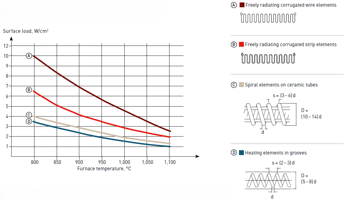
The more freely radiating the element form, the higher the maximum surface load. Therefore, the ROB (Rod Over Bend) type element can handle the highest load, followed by the corrugated strip element. The spiral type, being more concealed, has a lower maximum surface load. Spirals on tubes can carry a higher load than spirals in grooves.
The graphs below shows the recommended surface loads for Kanthal® and Nikrothal® alloys in industrial furnaces. Since Kanthal® alloys can be operated at higher temperatures than Nikrothal® alloys, a higher surface load can be accepted without jeopardizing element life. Element design is also crucial. The more freely radiating the element form, the higher the maximum surface load. Therefore, the ROB type element (corrugated heavy wire, mounted on the surface) can handle the highest load, followed by the corrugated strip element.
Coil elements on ceramic tubes can handle a higher load than coil elements in grooves. The values in the diagrams on page 51 are given for the following design conditions:
Element types A (heavy wire) and B (strip):
- Minimum strip thickness: 2.5 mm
- Minimum wire diameter: 5 mm
- Minimum pitch: 50 mm at maximum loop length and maximum surface load
Maximum recommended loop length:
- < 900°C: 300 mm
- 1,000°C: 250 mm
- 1,100°C: 200 mm
- 1,200°C: 150 mm
- 1,300°C: 100 mm
For finer wire diameters and smaller strip thicknesses, lower surface loads and shorter loop lengths must be chosen to avoid element deformation and subsequent
shorter element life.
Element type C:
- Wire element on ceramic tube
- Minimum wire diameter: 3 mm
Element type D:
- Wire and strip element in grooves
- Minimum wire diameter: 3 mm
- Minimum strip thickness: 2 mm
Maximum recommended surface loads for Nikrothal® alloys in industrial furnaces
Maximum recommended surface loads for Kanthal® A-1, Kanthal® AF and Kanthal® APM alloys in industrial furnaces
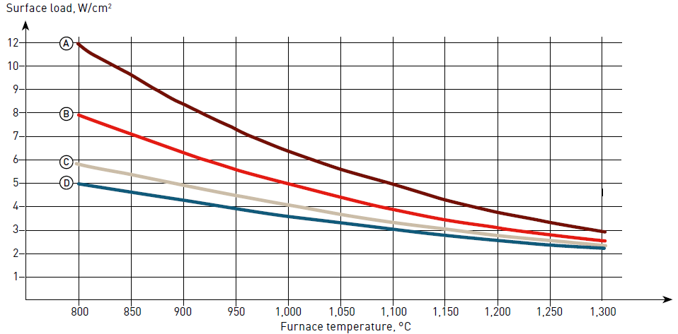
Note: The diagrams are valid for thyristor control. For on-off control lower surface loads should be chosen (about - 20%).
Design of wire elements
Calculations of wire: examples